

Product Catalogue
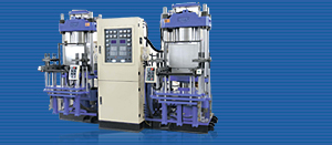
- Transfer Type Molding Machine
- Plate Vulcanizing Press
- Vacuum Vulcanizing Press
- Rubber Injection Molding Machine
- Transfer Type Molding Machine For Thermoset Plastic
- Rubber Mould
- Rubber Products

- Rubber machinery,
- hydraulic valve
- Plastic


Cartridge valve
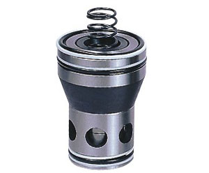
| A cartridge valve inserts the active element into the standard cavity of the manifold block and the cartridge is held in place by the passive block (the cover). It avoids the great deal of piping between the elements and actually eliminates any potential leakages and the consequential fluid waste. Cartridge valve merits Flexible system design; Low-cost installation; Small size; Improved performance, control and reliability; Higher pressure capacity; Better efficiency; Eliminated external leakage, reduced internal leakage; Better contaminant resistance; Faster cycles. Structure A cartridge valve is very much like a seated check valve and includes a plug assembly (cartridge) that slips into the cavity of themanifold block. The cavity is built per ISO7380. The plug is held in the cavity by the cover that is bolted onto the manifold block. THE cartridge is composed of the casing, the core, the spring and the seal. The cavity block holes connect the main passages A and B of the cartridge to other cartridges or working hydraulic systems. In the same principle, the cavity block holes connects the control passages X, Z1 and Z2 as necessary in accordance with arrangements in ISO7368. The control cover can also include a manual controller to limit core travel and flow rate. Various damping holes are provided so as to assist overall hydraulic system optimization or adjust the response of the cartridge valve. Some covers may also have an ISO4401 03 or 05 mounting face to make it possible to install the pilot-operated directional (or pressure) control valve as a whole piece. Adding control modules between pilot valves and the cover will extend control functions. Technical specification
Valve core area ratio Model instruction | ||||||||||||||||||||||||||||||||||||||||||||||||||
 |
 | |||||||||||||||||||||||||||||||||||||||||||||||||
 | ||||||||||||||||||||||||||||||||||||||||||||||||||
| Cover symbols | ||||||||||||||||||||||||||||||||||||||||||||||||||
  The users provide the function of the cover board and the position of the port (Please consult sketch map on the left side to complete the elements), then appoint the installing direction and the booster range of the pilot control valve. | ||||||||||||||||||||||||||||||||||||||||||||||||||


